
Unfortunately, the thinnest coloured wire I had available is still much too thick, but it works.

I colour coded the wires when I rewound the coil so I'd know which lead went where.

The coil itself is seen in the centre image. The coil bobbin holds the circuitry and the coils. The curved section of the pendulum houses a magnet (seen peeping out from the right side). The impulse repels the magnet, pushing it away.Ībove, you can see the components of the clock's motor system. This continues until the current can increase no further, at which point the transistor turns off completely (and rather abruptly - the 5.1k resistor is fitted to limit the maximum back EMF voltage swing which otherwise can easily reach 20 or 30 Volts). Once the transistor draws collector current (the red dot shows the collector), the current in the inner coil induces more current into the outer coil (connected to the base), turning the transistor on more. The direction that the pendulum is impulsed depends on the coil and magnet directions - it may occur on either left-to-right or right-to-left swings.Ī magnet is buried inside the curved section of the pendulum, and that induces a tiny current into the base of the transistor via the outer coil. The pendulum is pulsed once per complete swing (every 667ms). The pendulum rate is 3 beats/second (1.5 complete swings per second). The measured impulse duration is only 78ms, and with a peak current of 1.7mA, the average current drain is less than 200♚. These clocks are real power misers - at least with a silicon transistor. I did take a few measurements when I first used the silicon transistor. Since the movement is a 6 jewel type and is of good quality, it is actually worth the effort of restoring it IMO. The drive used now is external, because a silicon transistor is far too temperamental to use in such a simplified circuit.

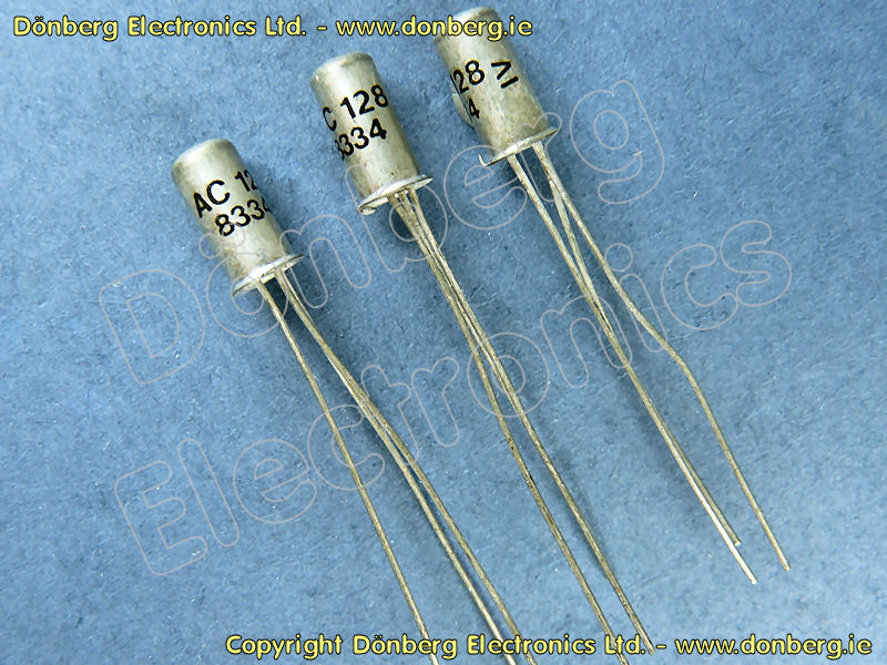
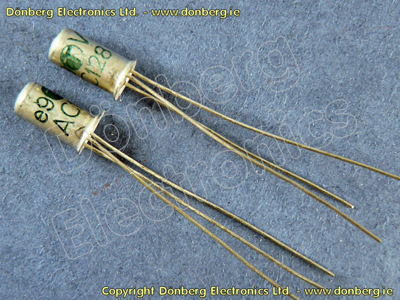
There is no doubt that the circuit works much better with a germanium transistor (ignoring the pendulum deflection which makes it unusable), but I don't have any of the old glass case types (such as the original TF65 pictured below the schematic), so I reverted to the silicon device for a while. The original transistor used a black painted glass case - these were common in the early days of English and European transistors, but are now unobtainable. This causes the pendulum to deflect alarmingly. Although fitting the circuitry is fiddly, I also tried an AC128 germanium transistor - bad move! As I discovered (after reassembling the motor), the cases of the AC128 transistors I have are steel (not aluminium as I had assumed) and are of course magnetic. the hands you see are only temporary!).Īlthough the original did indeed use a germanium transistor, I replaced it with a BC549 silicon device after rewinding the coils - mainly to find out if it would work (the battery polarity must be reversed if an NPN transistor is used). Nevertheless, the movement (pictured on the right) now works very well, and only awaits a case, face and hands (all of which were missing when I acquired it . This is not a fun job with 0.0635mm wire (#42 AWG/B&S), as the wire is so fine that it is difficult to avoid breakage - especially with several thousand turns. Unfortunately, the original coil was open circuit as well, so the clock required a complete rewind of the coil. This is not necessarily true, as I have replaced the germanium transistor with silicon in the once faulty Kundo movement, and it works just fine - albeit with some fairly pronounced caveats. These clocks always used a germanium transistor, and it is thought by many that silicon transistors simply won't work. The transistor used is PNP (as are most common germanium transistors). The circuit shown is the original version that I was unable to use after repairing the 'motor' coils, because the transistor was faulty. The basic schematic is shown, but note that there are many variations. These clocks use a pendulum that is kicked into continuous oscillation by a very simple circuit. To the left is the circuit diagram and the movement of a typical Kundo electric (Electronique) clock is shown on the right. The material here was finally updated in April 2014 (one can't rush these things after all). This was the first article in the horology section of the ESP site, and describes the repair of a Kundo (Kieninger and Obergfell) electronically switched electro-mechanical clock.


 0 kommentar(er)
